
Dynamic Cone Penetrometer (DCP)
A Dynamic Cone Penetrometer is a portable, hand-operated instrument that measures the in-situ strength of natural or compacted soil and unbound pavement layers. An 8kg hammer drives a hardened steel cone into the ground, and the penetration per blow is correlated to California Bearing Ratio (CBR) — giving engineers a fast, non-destructive read on subgrade and pavement strength without digging a test pit.
What Is a Dynamic Cone Penetrometer?

A Dynamic Cone Penetrometer (DCP) is a hand-operated field instrument used to assess the in-situ structural strength of road pavement layers, subgrade and compacted fill without excavating a test pit. A hardened steel cone is driven into the ground by repeated blows from a standard 8kg hammer falling 575mm, and the penetration recorded per blow — the Dynamic Penetration Index (DPI) or DCP Number (DN), in mm/blow — is inversely proportional to soil strength: a stiff, well-compacted layer might move only 3–5mm per blow, while a loose or weak layer can move 20mm or more.
Because it can be operated by one or two people with no external power source, the DCP is one of the most widely used field tests for pavement design, forensic pavement investigation and construction quality verification across South Africa, and its results are correlated to laboratory California Bearing Ratio (CBR) values through long-established empirical relationships.

Rapid & non-destructive
A typical profile to 850mm takes only a few minutes, avoiding the time and reinstatement cost of digging a test pit.
Continuous strength profile
Because readings are taken blow-by-blow, layer boundaries and weak or under-compacted zones show up as a clear change in slope on the penetration curve.
CBR correlation
Decades of published correlation studies allow DPI to be converted directly into an estimated in-situ CBR value for design or verification purposes.
Components of a Standard DCP Kit
Every dimension on the DCP is standardised so that results from one instrument are comparable with results from another, anywhere in the world. The Ecotao 1 metre kit ships complete and ready to use:

← Scroll to see full table →
| Component | Specification | Function |
|---|---|---|
| Handle & upper shaft | 16mm dia. steel, 575mm drop guide | Held to keep the unit plumb; guides the hammer's fixed 575mm free-fall |
| Hammer | 8kg (17.6 lb) sliding weight | Provides the standard impact energy for every blow |
| Anvil & coupling | Steel, threaded connection | Impact point that transfers hammer energy into the lower shaft |
| Lower shaft | 16mm dia. steel, graduated in 5mm increments | Carries the cone and provides the penetration reading scale |
| Cone | 60° hardened steel, 20mm base dia. | Standard penetrating tip; wear-rated and field-replaceable |
| Accessories | Measuring rod/rule, spanners, Allen keys, thread adhesive, carrying case | Assembly, field reading and safe transport |
Assembly & Pre-Test Preparation
- Join the shafts. Connect the handle to the upper shaft, and the upper shaft to the lower shaft via the anvil/coupling.
- Secure every joint. Use a non-hardening thread adhesive (e.g. Loctite) on all screwed joints — loose joints significantly shorten the instrument's life and introduce reading error.
- Inspect the cone. Check for visible damage, gouging or wear against the 20mm reference diameter before every test.
- Attach the scale. Fit the measuring rod or remote scale and confirm the hammer slides freely along the upper shaft with no binding.
Testing Procedure
A. Site Preparation & Seating the Cone
On bound pavement, cut a minimum 50mm hole through the surfacing and remove any water immediately to prevent saturating the unbound layer beneath. Place the DCP tip on the test surface, hold the device vertically, and tap the hammer from a partial height until the parallel-sided shoulder just above the tip sits flush with the surface. This ensures full imprint contact and bypasses disturbed surface material. Do not record penetration during seating — read and note the zero position only once seating is complete.

B. The Standard Testing Sequence
Repeat these four steps for every blow, keeping the shafts plumb throughout.
Plumb & Zero
Hold the shafts perfectly plumb without touching the lower shaft, and set a straight-edge reference point.
Lift
Raise the 8kg hammer slowly to the upper limit. Never lift the whole shaft with it.
Drop
Allow at least 2 seconds between drops and let the hammer free-fall cleanly onto the anvil.
Read
Read penetration to the nearest 1mm (or 0.1 inch) and log it against the blow count.

C. Adaptive Reading Frequency
How often to log a reading depends on how fast the layer is penetrating:
- Low-resistance layers (weak sub-base or subgrade): record every 1–2 blows so thin, weak spots aren't missed.
- High-resistance layers (granular bases, crushed stone): record every 5–10 blows, since penetration per blow is already small.
Stop the test if penetration is less than 3mm total after 10 consecutive blows, or if there is no measurable penetration after 20 consecutive blows. The DCP will not penetrate the layer — drill or auger through it to reset the datum and continue testing below.

D. Depth Limit & Termination
The standard 1 metre kit tests continuously to approximately 850mm. For deeper profiles, remove the overlying material with a pick or hand auger and restart from the new datum, or fit a 1 metre extension shaft to reach a recommended maximum of around 2 metres.
E. Extraction Protocol
Shallow Extraction
For shallow tests in soft material, the hammer may be lightly tapped upward against the handle to remove the unit.
Heavy Extraction
For deep penetration, place a jack tongue under the anvil and pump it out. Never force the unit out against the handle.

This accelerates wear and destroys welds. Use the jack method for any test with significant penetration.
Do's & Don'ts
Correct
Maintain strict plumb alignment via the top handle throughout every drop.
Keep hands clear of the anvil and hammer gap — beware of pinch hazards.
Allow the hammer's full kinetic energy to transfer freely into the anvil on every blow.
Incorrect
Never try to correct a tilted DCP mid-test. If it's severely off-vertical, abandon the hole and restart one metre away.
Never force the hammer down or restrict its natural fall.
Don't leave a tilted or binding shaft untreated in cohesive soils — rotate the device every few drops to prevent binding.

Data Analysis & the DCP–CBR Correlation
Plot penetration depth (mm) against blow count and the slope of that curve is the Penetration Index — DPI or DN, in mm/blow. A consistent slope indicates a uniform layer; a sharp change in slope marks a boundary between layers, or a hidden soft spot that a visual inspection would miss entirely.

This widely published empirical relationship converts a field DPI reading directly into an estimated in-situ CBR. Indicative values:
← Scroll to see full table →
| DPI (mm/blow) | Estimated in-situ CBR (%) | Typical material |
|---|---|---|
| 3 | ≈110 | Well-graded gravel / crushed stone base |
| 5 | ≈55 | Dense granular base |
| 8–10 | ≈22–30 | Select granular sub-base |
| 15 | ≈14 | Fair sub-base / stiff subgrade |
| 20–25 | ≈7–9 | Moderate subgrade |
| 38–48+ | ≈3–4 | Weak, soft or saturated subgrade |
Field DCP tests measure in-situ strength and may not correlate exactly with laboratory soaked CBR, which is tested under saturated conditions. Use the DCP result as a rapid field indicator alongside laboratory confirmation for final design decisions.


← Scroll to see full table →
| Soil / material type | Typical CBR range (%) | Typical DPI range (mm/blow) |
|---|---|---|
| Clay / silt | 2–17 | 15–127 |
| Select granular / sand | 17–45 | 6–15 |
| Class 3 special base / gravel | 53–100+ | 2.7–5 |
Loose sands and gravels give higher DPI values than well-compacted material of the same type — ranges assume adequate confinement. If field results substantially exceed these DPI limits, follow up with additional soil testing.
Maintenance & the Cone Wear Indicator
Replace the cone once its widest diameter has worn down by 5–10%, from 20mm to roughly 18–19mm.
Replace the tip immediately if it is visibly gouged or chipped by rock contact, regardless of measured diameter.
Wipe the upper and lower shafts clean with a soft cloth after every use. Lubricate the upper shaft very lightly with oil only if binding develops.

The DCP is a standardised testing device — its overall weight and dimensions must stay strictly within specification for results to remain comparable and valid.
DCP Testing for South African Pavement & Geotechnical Work
DCP testing is a standard, widely specified method in South African road and pavement engineering, used by consultants, contractors and municipal roads departments working to COTO/TRH pavement design guidance and forensic pavement investigation practice.
Road rehabilitation design
Profile existing pavement layers before an overlay or reconstruction design, identifying weak layers and layer boundaries without cutting trial pits along the route.
Subgrade & building platform verification
Confirm compacted fill and subgrade CBR on commercial, industrial and residential developments ahead of foundation or slab design.
Mine haul roads & laydown areas
Quick, repeatable in-situ strength checks across large unpaved haul road and yard areas where laboratory testing every point is impractical.
How to Choose the Right DCP Setup
Most site investigations only need the standard kit. Consider the extras below based on the depth and volume of testing your project requires.
← Scroll to see full table →
| Requirement | Recommended setup |
|---|---|
| Pavement or subgrade testing to ≈850mm | Standard 1 metre DCP kit (DCP1M) — sufficient for the large majority of road and building-platform investigations |
| Deep fill, mine haul road or full pavement profile to ≈2m | Standard kit plus 1 metre DCP extension shaft |
| High test volumes on abrasive gravel or crushed stone | Keep 1–2 spare cone tips on hand — tips wear faster in coarse granular material |
| Soft, cohesive soils or shallow hand-probe checks only | A lighter hand penetrometer (e.g. a pocket penetrometer) may be more appropriate — the DCP is built for pavement-grade materials, not fine index testing |
DCP Kit & Accessories

Dynamic Cone Penetrometer (DCP) — 1m
Complete 1 metre DCP kit with 8kg hammer, one cone tip and carrying bag. Tests continuously to approximately 850mm.
Check Stock & Enquire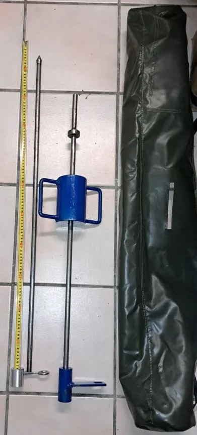
1 Metre DCP Extension Shaft
Extends the standard kit to a recommended maximum test depth of approximately 2 metres for deep fill and full pavement profiles.
Check Stock & Enquire
Replacement DCP Cone Tip
Standard 60° hardened steel cone, 20mm base diameter. Keep spares on hand for high-volume or abrasive-ground testing.
Check Stock & EnquireFrequently Asked Questions
What is a Dynamic Cone Penetrometer (DCP) used for?
It measures the in-situ strength of natural or compacted soil and unbound pavement layers by recording how far a standard cone penetrates the ground per hammer blow. The result (DN or DPI, in mm/blow) is correlated to CBR and used for road pavement design, forensic pavement investigation and subgrade verification.
How does DCP penetration relate to CBR?
Lower DPI values indicate stronger material because the cone penetrates less per blow, while higher DPI values indicate weaker, looser material. The published relationship log CBR = 2.46 − 1.12 × log DPI converts a field reading into an estimated in-situ CBR for each layer.
How deep can a DCP test go?
A standard 1 metre DCP tests continuously to approximately 850mm. Adding a 1 metre extension shaft allows testing to a recommended maximum of around 2 metres.
When should the DCP cone be replaced?
Once its 20mm base diameter has worn down by 5–10% (to roughly 18–19mm), or immediately if the tip is visibly gouged or damaged from rock contact.
Why does the DCP sometimes stop penetrating?
This is the refusal condition: penetration of less than 3mm over 10 consecutive blows, or none at all after 20 blows, means the layer is too strong for the DCP. Drill or auger through it to reset the datum and continue below.
Do I need the DCP extension shaft?
The standard 1 metre kit is sufficient for most shallow pavement and subgrade investigations. Add the extension when a project needs testing below approximately 850mm — deep fill verification, mine haul roads, or full pavement structure profiles to 2 metres.
Need a DCP for Your Next Site Investigation?
Speak to our team about the standard 1 metre kit, extension shafts and replacement cone tips — in stock and ready to ship across South Africa.
Head Office: +27 21 911 5835 | Zak: 086 142 8716 | Zaid: 082 390 3989